Introduction
Neodymium-iron-boron-magnets (Nd-Fe-B) are so-called rare earth magnets distinguished by their very high energy densities. Thus, they are constantly gaining importance in the age of electric mobility and miniaturization and particularly in application areas in which strong magnetic fields at low volumes and low weights are necessary. An increasing focus is on resource conservation of raw materials, weight reduction of the drives and longer service lives of permanent magnets. For example the use of Nd-Fe-B-magnets can make miniaturization in sensor technology possible. Their use in engine construction leads to a reduction of the size of subassemblies and consequently a reduction of volume and weight. In this way, amongst other things, smaller and/or more powerful electric motors with a higher efficiency degree can be manufactured using magnets with higher energy densities.
It is possible to make further improvements to magnets currently being manufactured by using structures with finer particles to obtain an even grain growth during sintering. While structures with finer particles increase the coercive field strength, coarser structures contribute to the obtaining of high remanence due to their better orientation behavior. This means that the rare earth powders used must have the narrowest possible particle size distribution. A narrow particle size distribution with the lowest possible proportion of finest- (< 2 µm) and coarsest particles (> 8 µm) is ideal. The sinter conditions are also decisive for the quality of the magnets and must be carefully optimized. The use of clean raw materials and ideally inert conditions during processing to keep contamination to a minimum are of equal importance.
The solution from NETZSCH
Spiral Jet Mill m-Jet with integrated dynamic Air Classifier
NETZSCH has developed a new mill especially for grinding rare earth alloys.
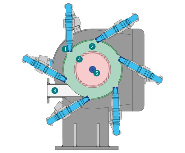
The m-Jet (Fig. 1) comjkabines the advantages of a fluidized bed jet mill with those of a spiral jet mill and is therefore the ideal mill for grinding rare earth powders. The combination of a spiral jet mill with a dynamic air classifier makes it possible to obtain highest reproducible fineness independent of the load in the gas jets.
The grinding gas is conveyed to the grinding chamber (2) via a ring-shaped grinding gas distribution system and the nozzles (1) where it is expanded during which high-speed jets are formed. The product to be ground is transported tangentially into the grinding chamber (2) by an injector or gravimetrically through a lock via a connection piece (3) where it is taken up by the gas jets, accelerated and ground by particle-to-particle impacts. The stressed particles are then transported to the classifier wheel (4) with the grinding gas. The classifier wheel is driven by an infinitely variable motor. The fine product which corresponds to the set conditions is discharged out of the mill with the expanded gas (5); product which is too coarse is returned to the area of the jets to be impacted again. The circular movement of the product in the grinding chamber facilitates the charging of the jets with particles.
Due to the differences in design, the product content during grinding phase of an m-Jet is 20 to 25 times lower than that of a correlated fluidized bed jet mill. Due to this fact, practically no fluctuations in throughput capacity and especially in the particle size distribution occur during start and stop of the plant. A selective grinding of individual alloy components does not take place (Fig. 2).

A further advantage of the m-Jet compared to the fluidized bed jet mill is the possibility of the automatic rejection of components which are difficult to grind or the switching to another product. Undesirable components can be removed directly from the grinding chamber during operation of the mill (Fig. 3). This requires only a few seconds. The overpressure in the mill ensures that components which are difficult to grind are transported into the filter. In this way the classifier wheel is bypassed by changing the position of the discharge pipe in the housing of the mill. It is possible to determine the decrease in throughput capacity due to components which are difficult to grind via the duty cycle of the dosing. When a certain value is reached the product is rejected and removed. In this way, there is absolutely no problem caused by contamination of the product-conveying piping with coarse product particles and/or components which are difficult to grind. Thanks to the small volume of the grinding chamber powder losses which occur during changing of the product are extremely low.

Advances in the Manufacture of Nd-Fe-B-Powders by Classifying
The undesirable finest fractions in ground rare earth powders can be separated out by classifying after grinding. Classifying under inert conditions can either be carried out offline or inline. For this purpose, two basic plants and classifying systems are available. Offline classifying can be carried out with the NETZSCH High dispersion classifier m-Class and inline classifying with the ultra-fine classifier InlineStar M. Both classifier executions have been optimized for the classifying of rare earth powders. NETZSCH has applied for a patent for the process of grinding with downstream classifying of rare earth powders.
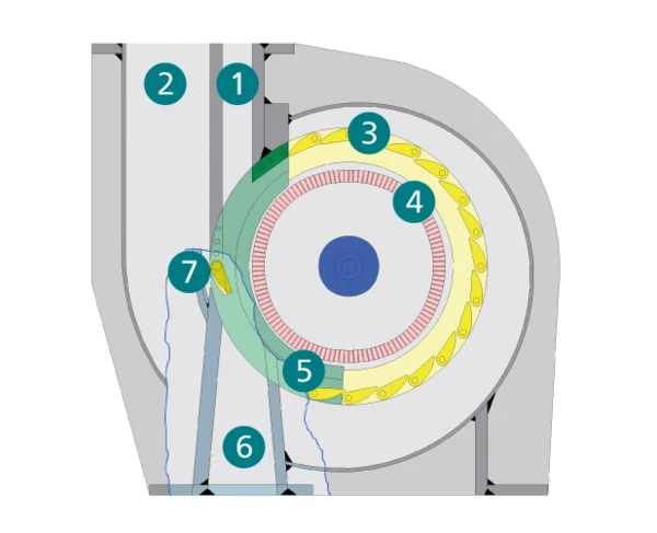
In offline-classifying the product is fed into the classifier from above via a dosing unit and the product feed unit (1). The necessary process gas is supplied via the classifying gas inlet (2). The process gas disperses the feed product extremely thoroughly through the large number of adjustable guide vane gaps of the static guide vane basket (3) and then offers it to the classifier wheel (4). Here the separation of coarse and fine products is carried out according to the set classifier speed (infinitely variable). The “fines” leave the machine via the classifier wheel which is installed on a horizontal shaft at the center of the classifier. “Coarse particles” are rejected by the classifier wheel and are discharged at the rear via the coarse product outlet (6) on the lower side of the housing which is spiral-shaped and has a dividing wall (5). By adjusting the so-called coarse product flap (7) the discharge of coarse product for difficult separation applications can be regulated to influence the “purity” of the coarse product.
For the first time Nd-Fe-B-powder which has either no undesirable finest- or if required no coarse fraction could be produced thanks to the subsequent classifying step. If the product is classified twice then both finest- and coarse fractions can be eliminated if desired and thus the particle size distribution of the powder exactly adapted to suit the particular application.
Results of subsequent Classifying of Rare Earth Powders and their Influence on the Properties of Nd-Fe-B-Magnets
By classifying after grinding undesirable finest- or coarse particles can be deliberately removed from the ground product. The desired amount of fines can be separated out by changing the classifier speed or the gas volume flow through the classifier. A decisive factor for this is an excellent dispersion of the product in the gas stream. This must be guaranteed so that the classifier can select the particles cleanly so that the best yields and steep particle size distributions can then be obtained.
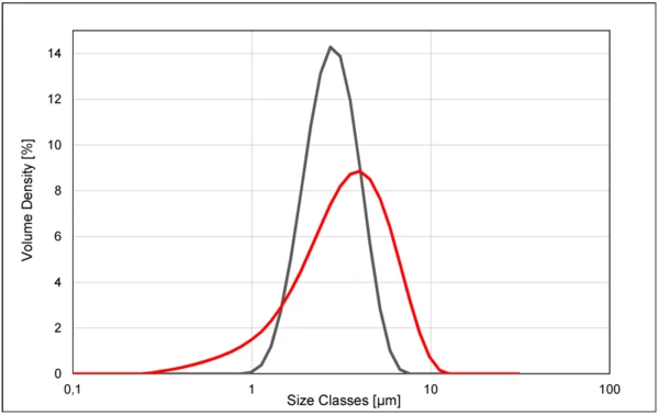
Fig. 5 shows the differences in the particle size distributions of a product which was only ground and one which was subsequently classified. The d10 value increases from 1.54 µm to 2.03 µm. The fraction of finest particles < 1 µm is around 2.8 % before classifying and almost 0.00 % after classifying.

In recent years, the so-called ‘target jet mill’ was also introduced for grinding of Nd-Fe-B-powder. The difference in the width of the PSD of a sample manufactured on an m-Jet mill with subsequent classifying on an m-Class compared to that of a product conventionally manufactured on a target mill can be seen clearly (Fig. 6).
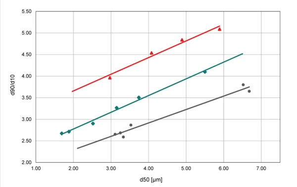
To obtain a comparison of the d90/d10-ratio, samples with various d50-values were ground and were then classified. The results showed that the d90/d10 value of the classified samples was considerably better than that of the samples which had only been ground. At a d50 of 3.0 µm values of 2.6 were obtained. Compared to this, for an unclassified product with the same d50 a value of 3.2 for an m-Jet or classic fluidized bed jet mill was obtained. The target jet mill results were around d90/d10 = 4.1 and therefore nearly double that for the powder which had been both ground and classified (Fig. 7).
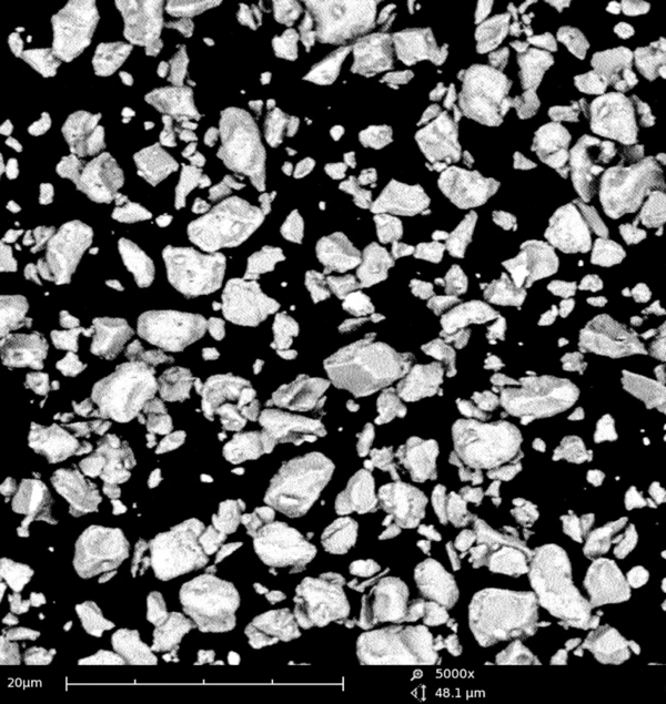
This is also made clearer by looking at the differences in the REM-images of ground powder in comparison to ground and classified Nd-Fe-B-powder. Fig 8 shows the image of the ground powder with a clearly recognizable finest fraction, on Fig. 9 the sample which has also been classified and which contains only a negligible finest fraction.

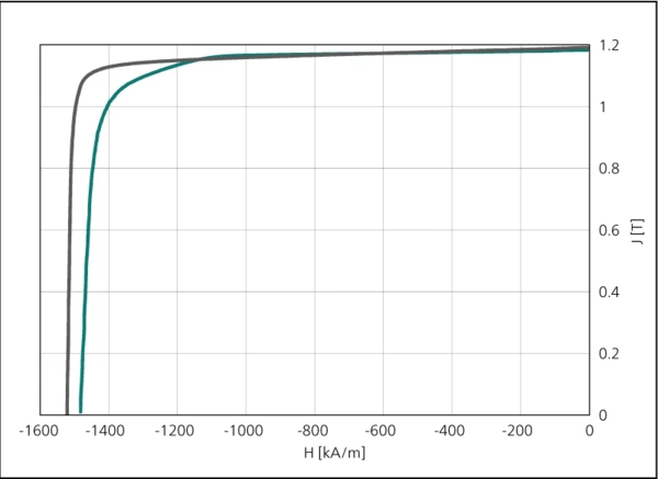
To examine the influence of a narrower particle size distribution on the magnetic properties, magnets were manufactured under differing sinter conditions. The analysis of the results showed that magnets made of classifier powders have higher coercive field strengths. The knee-field strength Hk and the rectangularity R = Hk/Hcj also improved significantly (Fig. 10).
A connection between the steepness of the PSD (d90/d10) und the rectangularity of the demagnetization curve can also be seen clearly. The rectangularity behaves inversely proportional to d90/d10. Therefore, narrower particle size distributions increase the rectangularity of the demagnetization curve.
Conclusion
The sinter tests showed that magnets with good magnetic properties could be produced with Nd-Fe-B powders ground on the spiral jet mill m-Jet. Therefore, the m-Jet can offer a real alternative to fluidized bed jet mills which have previously been almost exclusively used. Furthermore, it was also possible to show that Nd-Fe-B-fine powders which had been subsequently classified after the usual processing before sintering could be used to manufacture anisotropic magnets with good magnetic properties. High coercive field strength and the improved rectangularity of the demagnetization curve indicate that these magnets have a more homogeneous structure than comparable conventional magnets.
In Hanau near Frankfurt in Germany, NETZSCH Trockenmahltechnik has a well-appointed laboratory for tests with rare earth powders. In this lab, it is possible to carry out grinding tests on the fluidized bed jet mill of type CGS and on the spiral jet mill with integrated classifier of type m-Jet as well as classifying tests under inert atmosphere (nitrogen) on the High dispersion classifier m-Class. Many different analyses such as e.g. laser particle analyzer (Malvern) and REM can also be carried out in Hanau as well as ONH, OCN, ICP analyses in cooperation with a renowned institute.